


Ignatz,
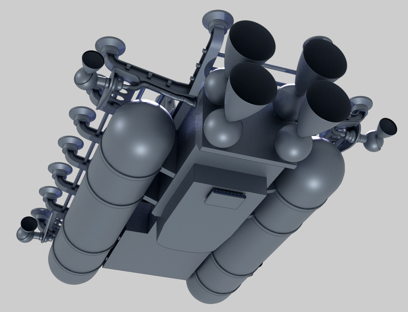
Oh, that's wonderful! The pin is so big and robust, it's easy to believe it can be used to move a lot of mass. And the thruster cones are just perfect. Exactly the size and shape I'd imagine they would need to be.
You've done so much fine work on this. I'm very, very grateful! There is zero rush here, so don't hesitate to take care of all the other stuff in life. Space will still be there, waiting.
Talk to you soon,
-David
Mon, Feb 22, 2021 at 10:51 AM
David,
I found time to mount those thrusters to the GM Box Hauler.
The ship designers seem to have added the thrusters as an afterthought and so have routed the power to them via external, armoured conduit.
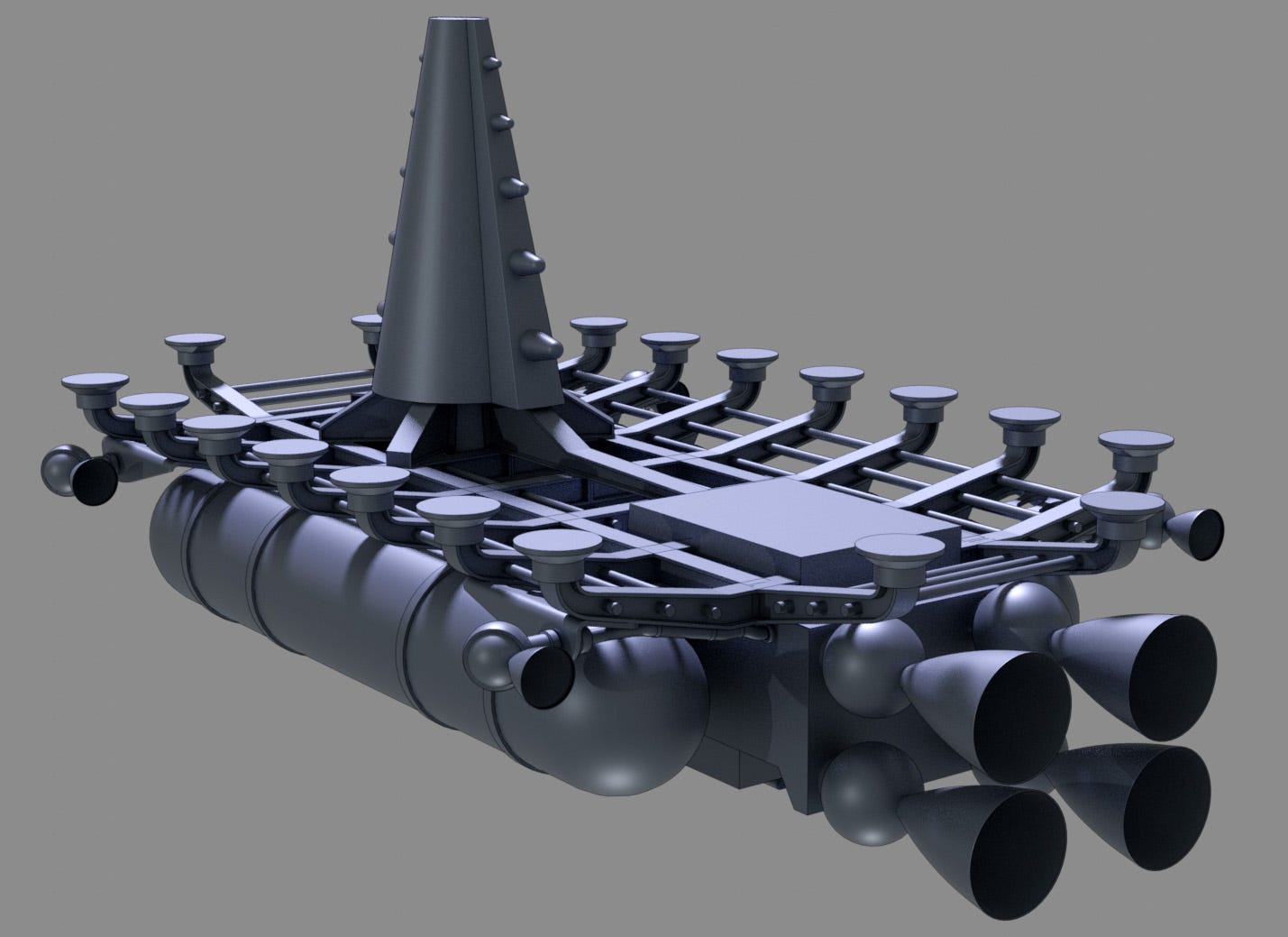
The thrusters are so arranged that they can rotate 360° around their mount points and even swivel to enable the thruster nozzles to point out to the side, perpendicular to the main axis of the ship.
Obviously, the thrusters are necessary for manoeuvring the ship in space and especially during the link-up procedure with the cargo container. Whether they have enough 'oomph' to allow for quick course changes when hauling a heavy load is another issue you might have to take up with the tech crew at the shipyard.

The designers had intended to build a second generation of this vessel (before the box hauler class was made obsolete) in which an extra manoeuvring thruster was to be mounted on a pylon descending down from the second deck in line with the locking tower. That thruster would have been fully as large as one of the main engines, able to swivel and direct its thrust in any direction within a half hemisphere extending downwards from the plane of the support rack. This would have given the haulers much more control of really large loads.
There is also a hidden feature in that locking tower. The tower is mounted on a column around which is can rotate and lock in discrete locations. That column is also attached to an immense hydraulic unit which is used to apply tension to that column so as to pull the Box Haul tightly against the cargo container. In addition to that tension on the locking tower, the pads on the top of the support rack are magnetic. Once the locking tower is firmly engaged the magnetic force in the pads is engaged to finish making the entire hauler 'one' with the cargo container. When it comes time to slow down the cargo container at the end of a run the power to those magnetic pads is cut at which time the entire ship is able to slightly release the tension between itself and the cargo, allowing it to rotate around the tower (which is still firmly locked to the container) a full 180° at which point the tension is reapplied and the pads once again locked to the surface of the container for that extra support. Now the box hauler is oriented with the main engines pointing in the direction of motion and can serve as brakes. Wow!
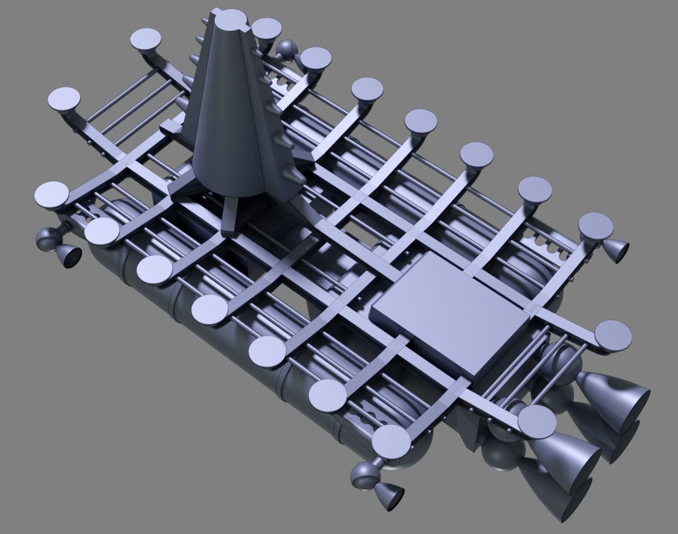
I was also thinking there is a fair amount of space between the top of the pads that contact the container and the supporting beam structure below. I would envision this area as being ideal for locking down a few of the 'necessaries' such as scoots, extra line and so forth. Sort of like the usual running gear on a sailing ship.

And now back to our reality sphere...
Obviously, I can get as crazy as you like with the detail and such, but I think we should avoid overkill. So the question is: where and how do you intend to use this as an illustration? What would you like to see? Do you want full color? Deep space sky background? Planets? Extra jam and pancakes?
Let me know.
Cheers,
- Ignatz